3.1 Have the comm. cables between modules been connected properly?
3.2 Has the terminating resistor been installed on the last level battery module?
3.3 Is the comm. cable between Power Module and Backup Controller connected correctly?
4.1 Is the AC wiring of the Power Module secure?
4.2 Pay attention to the neutral-ground bonding strap
4.3 Are the position and direction of the CTs correct?
5.3.1 Do not operate this switch
5.3.2 Select a good Wi-Fi network
5.3.3 Choose the time zone right
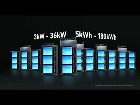
0. Preface
Completing the installation of Anker SOLIX X1, please check the installation and wiring according to this document to avoid errors before and during powering on.
|
Doc Type |
AC-Coupled |
|
Installer Manual | |
|
Video |
Note: To view the manuals and videos, you can also scan the QR codes in the up-right corner of the Quick Installation Guide in the package.

1. Before Checking
It is recommended not to fix the wiring compartment cover and the side cover on the right side of the Power Module until finishing commissioning, in order to check the wiring conveniently.

2. Structure Installation
2.1 Supportive Base
If the system is wall-mounted, make sure the baseplate and bracket holders has been installed.
If the system is floor-mounted, make sure the floor mounting base has been installed. (This base is not included in the package and needs to be purchased separately)
|
Baseplate+Bracket Holders (A5674AZ1)(Included) |
Floor Mounting Base (A5670AZ1) |
|
|
|


2.2 Side Covers
Due to the different production batches, there are two types of battery side covers, legacy and new. The ways to install them are different.

2.3 Wiring through conduits
The wiring exposed outside (e.g. the comm. cable between Power Module and Backup Controller) must be through the conduit.

Note: Exposed cables may not only be easily damaged, but also affect the sealing of the equipment, and condensation may occur inside the equipment.
3. Communication Wiring
3.1 Have the comm. cables between modules been connected properly?
Check if the comm. cables between Power Module-Battery Module, and Battery Module-Battery Module, are properly connected.
Gently pull the cables to ensure they are installed firmly.

3.2 Has the terminating resistor been installed on the last level battery module?
Check the last level battery module, the BAT +/BAT- ports should have dustproof caps installed, and the BMS port should have a terminating resistor installed.
Gently pull the resistor to ensure it is installed firmly.

Note: If the terminating resistor is not installed, the system may report fault A5.
3.3 Is the comm. cable between Power Module and Backup Controller connected correctly?
|
Power Module side |
Single PM scene |
Comm. cable should connect to the PCS_COM1 |
|
Multiple PM scene |
Comm. cable should follow the principle "PCS_COM2 in,PCS_COM1 out" The DIP switches 1, 2, and 3 of the first Power Module should be turned ON. | |
|
Backup Controller side |
Comm. cable from the Power Module should connect to the COM_PCS port | |

Ports on Power Module (left) and Backup Controller (right)

Single PM scene

Multiple PM scene
Note: If the communication cables are not properly connected, or the DIP switch is not set correctly, the system cannot correctly identify the device.
4. Power Wiring
4.1 Is the AC wiring of the Power Module secure?
The cables are recommended to be crimped to the terminal. Fixing screws of cables should be tightened. Gently pull the cables after installation to ensure they are firmly connected.

Note: If the wiring is not secure, the AC supply of the Power Module will be affected. The Power Module may go black and unresponsive.
4.2 Pay attention to the neutral-ground bonding strap
When the backup controller is the main service equipment, install the bonding strap.

When the backup controller is NOT the main service equipment, remove the bonding strap.
4.3 Are the position and direction of the CTs correct?
CT1 and CT2 cannot exchange positions. CT1 must be installed on the L1 line, and CT2 must be installed on the L2 line. The arrows on the CTs should point to the grid.
|
When the backup controller is the main service equipment |
When the backup controller is NOT the main service equipment |
|
|
|


Note: If the CTs are installed in the wrong position, it may cause the system power calculation to be incorrect and cannot run normally.
4.4 Has the BAT switch been OFF if the commissioning cannot be completed immediately after installation?
If the system has been installed but the commissioning with App cannot be completed on the same day, please turn the BAT Switch (on the left side of the Power Module) to OFF.

Note: If the BAT Switch is not turned off, the battery module will continue to discharge to power the Power Module. Long-term discharge may cause over-discharge, resulting in battery module damage.
5. Commissioning
5.1 App
Commissioning needs Anker SOLIX Professional app. This app is exclusively for installers to commission the system, not a "Pro version" of the Anker app.
5.2 Before Commissioning
-
Check the installation and wiring as mentioned above.
-
The system cannot be commissioned off-grid. So make sure it can connect to the grid.
-
Turn on the breakers and switches in this order: (Power Modules) BAT Switch - (Backup Controller) PV, generator and Power Module Breakers - (Backup Controller) Grid-side Breaker.

5.3 During Commissioning
5.3.1 Do not operate this switch
There is a white switch in the Backup Controller. Do NOT toggle this switch after the Backup Controller is powered-on.

Note: If this switch is operated after the Backup Controller is powered on, it may cause the commissioning to fail, and the system reports an A44/A45 grid-side relay fault. If this happens, the system needs a full restart to recover.
5.3.2 Select a good Wi-Fi network
The strength and the quality of the Wi-Fi network make a difference on the communication of the system. Make sure the installation location has good 2.4GHz Wi-Fi。 If not, it is recommended to use an Ethernet cable.
5.3.3 Choose the time zone right
The time zone setting determines how the system senses the time. If chosen wrongly, work modes depending on time periods like Time-of-Use may not work normally.
5.3.4 Common Fault Codes
|
Code |
Fault |
Possible reason |
Suggestion |
|
P78 |
Grid Phase Fault |
L1 and L2 cables between PM and BC may connected in reverse. |
Ensure the sequence of L1 and L2 is correct. |
|
A69 |
Grid Loss |
The grid is disconnected. |
Check if there is a power outage and verify whether the grid circuit breaker of the backup controller is turned on. |
|
A99 |
Power Disconnected |
Power cables between PM and BC is disconnected. |
Check power cables and circuit breakers between PM and BC. |
|
A41 |
PCS Communication Failure |
PM is powered-off. The communication between BC and PM is disconnected. |
Check that the RJ45 cable between BC and PM is properly connected. Additionally, ensure that PM has been powered on both the DC side (BAT Switch on the PM) and the AC side (circuit breaker inside the BC). |
|
A100 |
Signal Lost |
The backup controller can't communicate with some of the power modules. |
Check that the RJ45 cable between the PMs is properly connected. Ensure that PMs are powered-on. |
|
A3 |
Wireless Module Communication Failure |
Wireless Module Communication Failure |
Ensure that the WLAN Dongle/4G Dongle is securely installed and functioning properly. |
|
A64 |
Abnormal Wireless Module Comm. |
(Microinverter scene) The Zigbee Dongle cannot communicate with the Backup Controller |
Ensure that the Zigbee Dongle of the microinverter is on the same Wi-Fi local area network (LAN) as the backup controller and that it can communicate properly. |
|
A30 |
PV Overload |
The current system is off-grid, and the photovoltaic (PV) power is too high, so the system needs to shut down the PV. |
- |
|
A58/A59 |
Grid L1/L2 CT Fault |
The grid CT (current transformer) is installed incorrectly. |
Check the installation of CTs. |
|
A5 |
Battery Module Communication Abnormal |
Battery communication cable is installed incorrectly. Or the battery has entered sleep mode. |
Check the battery communication cable and and whether the battery is in sleep mode. |
6. Before Leaving
Take enough photos after installation for future inspection purposes.
|
Final site photo (get a good angle of the entire completed installation) |
|
|
Mounted X1(s) (get a good angle and take a few differents) |
|
|
Battery Module side plane view (cable connections) |
|
|
Power Module side plane view (cable connections) |
|
|
Mounted Backup Controller (opened, for wiring QA) |
|
|
Main panel / service breaker |
|
|
PV inverter (Optional) |
|
|
Generator (Optional) |
|
|
High power load on this site (Optional) |
E.g. Air conditioning |
|
Anything unique on this site |
E.g. Special environment |