2)Precautions for filling in NMI
3)The Bluetooth cannot be detected at commission
4)Unable to connect to Bluetooth at commission
7)After adjusting the device wiring, it is necessary to restart the device.
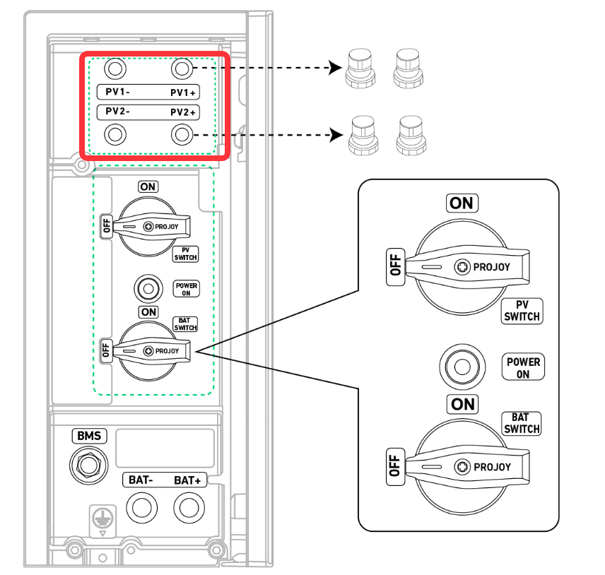
8)At the initial stage, all switches must be set to the "on" position.
9)Operation of equipment while it is powered on is not allowed
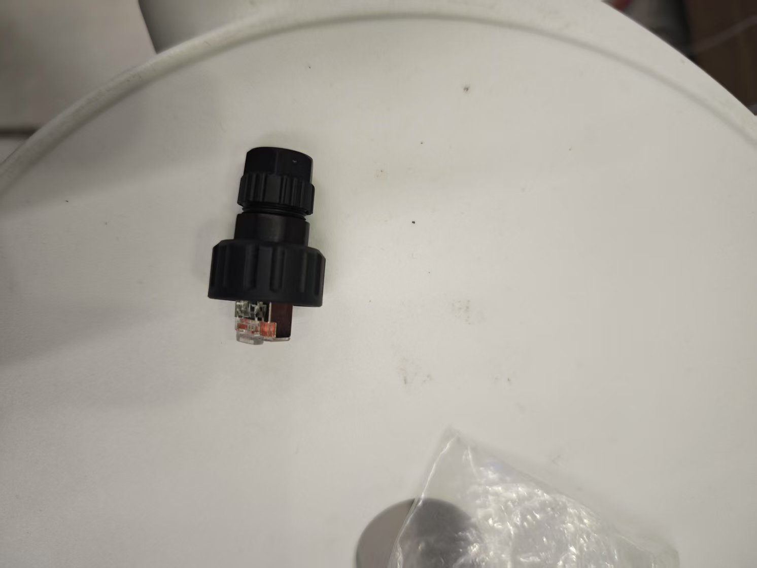
10)How to disassemble the AC-grid terminal and the AC-backup terminal
11)Pre-start Preparations for Initial Startup
12)Base Baffle Installation Instructions
I. General skills
1)SOP of Upload log:https://support.ankersolix.com/s/article/How-to-Upload-a-Log
When a malfunction occurs, be sure to upload the APP logs and Device logs immediately.
2)SOP for Device Restart:https://support.ankersolix.com/s/article/How-do-I-Restart-Anker-SOLIX-X1-Australia
3)Installer Guide:
https://support.ankersolix.com/s/articlemanual?pn=A5102B&utm_source=qrcode&utm_medium=psg
4)The common precautions for device replacement:https://support.ankersolix.com/s/article/Common-Issues-After-Device-Replacement#section-1
5)Power Sensor Wiring Diagram:
https://support.ankersolix.com/s/article/Anker-Solix-X1-Meter-Wiring-Diagram-AU
The power sensor and CT must be purchased from Anker or its authorized channels; otherwise, the project may not be able to go live due to unsupported meter types.
II. Troubleshooting
1)A60 fault
Abnormal performance: The system reports Error Code A60, indicating a “CT fault on the grid-side meter”.
Possible Cause: Wiring error of the CT of the electricity meter on the grid side.
Suggestion: Adjust the wiring of the electric meter. For specific wiring scenarios, please refer to:https://support.ankersolix.com/s/article/Anker-Solix-X1-Meter-Wiring-Diagram-AU
2)A6 fault
Abnormal performance: The system reports Error Code A6, indicating a “Grid Meter Communication Failure”.
Possible Cause 1: The grid meter communication line is connected to the wrong position.
Suggestion: Connect the meter communication wires correctly. For specific wiring scenarios, please refer to:https://support.ankersolix.com/s/article/Anker-Solix-X1-Meter-Wiring-Diagram-AU
3)A7 fault
Abnormal performance: The system reports Error Code A7, indicating a “PV Meter Communication Failure”.
Possible Cause 1: The PV meter communication line is connected to the wrong position.
Suggestion: Connect the meter communication wires correctly. For specific wiring scenarios, please refer to:https://support.ankersolix.com/s/article/Anker-Solix-X1-Meter-Wiring-Diagram-AU
4)A5 fault
After adjusting the device wiring, it is necessary to restart the device.
Abnormal performance: The system reports Error Code A5, indicating a “Battery Module communication failure”.
Possible Cause 1: Accidental Triggering of Device Buttons.
Suggestion: Press and hold the Power button for 3–5 seconds to try to activate the battery. If activation is successful, contact the Anker After-Sales Service Center to upgrade to the new firmware.
Possible Cause 2: The wiring between the two battery module stacks is loose.
Suggestion: Adjust the wiring between the two battery module stacks.
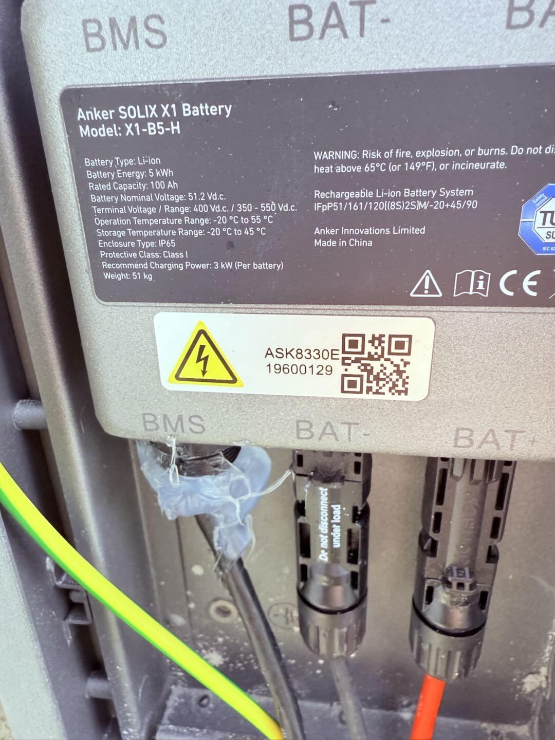
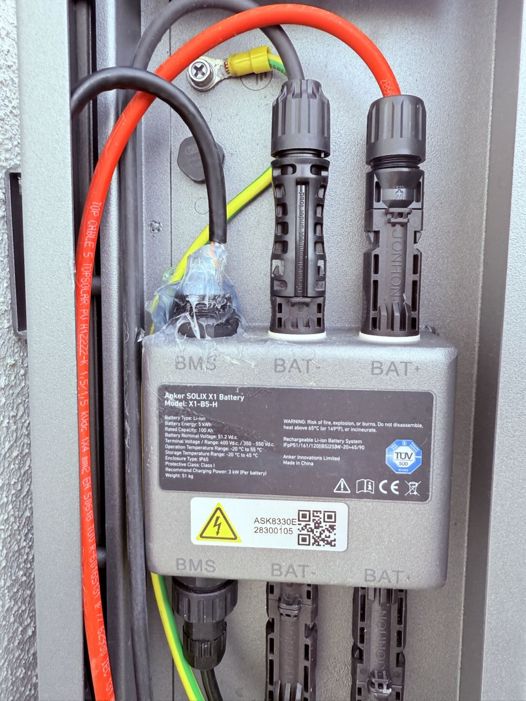
Possible Cause 3: The 120-ohm resistor is not connected to the battery at the very end.
Suggestion: Connect the 120-ohm resistor to the battery at the very end.
5)P81 fault
Possible Cause 1: Grid abnormality.
Suggestion: If there is an actual power outage in the grid, please be patient and wait for the grid to return to normal.
Possible Cause 2: If the P81 fault is accompanied by circuit breaker tripping, it is usually because the current-carrying capacity of the circuit breaker does not meet the system requirements.
Suggestion: Lower the peak shaving value to avoid circuit breaker overcurrent.
Possible Cause 3: The wiring from the household entrance to the AC grid port of the X1 device is abnormal.
Suggestion: The installer should come on-site to inspect the wiring, including checking for loose connections and verifying if the phase sequence is correct.
6)System tripping
-
Measure the voltage and impedance at the AC grid circuit breaker, both before and after the breaker.
-
Measure the voltage and impedance at the AC backup circuit breaker. If the backup switch is off, only measure the data on the side close to the PCS; if the backup switch is on, measure both before and after the breaker.
-
During the measurement process, simultaneously check the wiring of the AC grid and AC backup.
-
If no abnormalities are found in steps 1, 2, or 3, turn off the PV and battery, and connect only the utility power. Observe whether the PCS screen is normal. If it is abnormal, this indicates a problem with the PCS. If it is normal, it is most likely an issue with the PV wiring. Check the PV wiring.
7)P36 fault
Abnormal performance: The system reports Error Code P36, indicating a “Grid Interconnection Relay Fault”.
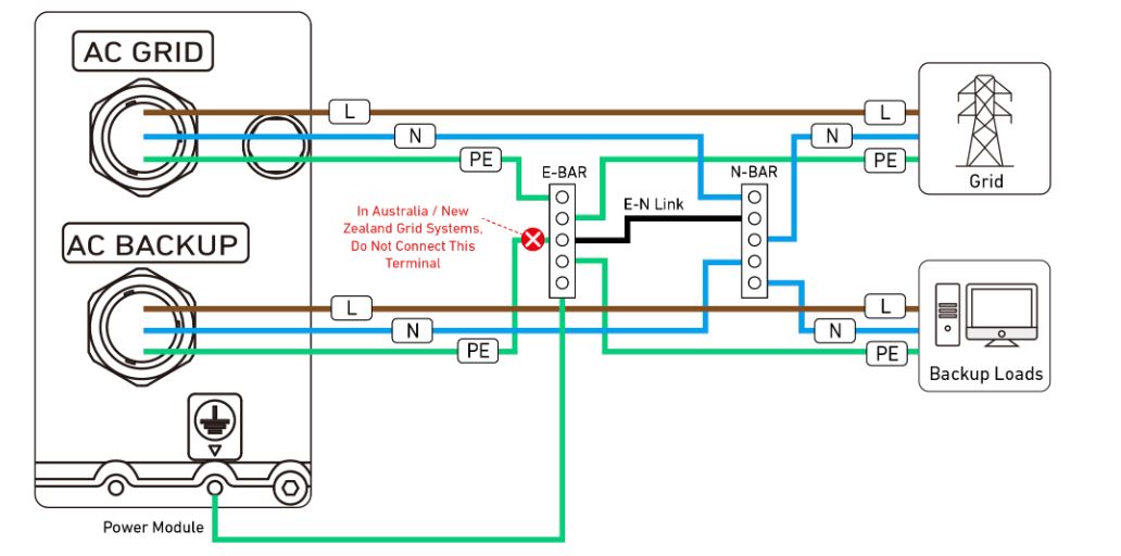
Possible Cause 1: The PE wire of the AC-backup port is connected to the E-BAR.
Suggestion: Disconnect the connection between the PE wire of the AC-backup port and the E-BAR.
8)Self-check timeout
Possible Cause 1: Communication issue with the grid-side electric meter. The system reports an A6 fault, which can be viewed in detail on the main page of the installer’s app at the top right corner.
Suggestion: Refer to point 1 for handling suggestions regarding the A6 fault.
9)P53/P54 fault
Abnormal performance: The system reports Error Code P53/P54, indicating a “PV1 overvoltage / PV2 overvoltage”.
Possible Cause 1: Excessive number of PV panels configured.
Suggestion: Reduce the number of PV panels. The number of PV panels should be configured as follows: Number of PV panels = System voltage upper limit (600V) / Open-circuit voltage of a single PV panel / 1.1. Round down the calculation result to the nearest whole number.
10)P55/P56 fault
Abnormal performance: The system reports Error Code P55/P56, indicating a “PV1 reverse connection / PV2 reverse connection”.
Possible Cause 1: The PV1- terminal is connected to the PV1+ port on the Power Module, and the PV1+ terminal is connected to the PV1- port on the Power Module; the PV2- terminal is connected to the PV2+ port on the Power Module, and the PV2+ terminal is connected to the PV2- port on the Power Module.
Suggestion: Adjust the PV wiring: Connect the PV1- terminal to the PV1- port on the Power Module, and connect the PV1+ terminal to the PV1+ port on the Power Module; connect the PV2- terminal to the PV2- port on the Power Module, and connect the PV2+ terminal to the PV2+ port on the Power Module.
III. Common precautions
1)AC-backup port overload
If a load needs to be connected to the AC-backup port, the load must be less than the maximum output power of the AC-backup port for the installed model.
Maximum output power of the AC-backup port for each model:
X1-H5K/6K-S: 7.36kw/32Aac
2)Precautions for filling in NMI
-
South Australia
Select SAPN
-
Victoria
Select Ausnet/CITI POWER / Powercor / United Energy/Jemena
-
Western Australia
Select Synergy
3)The Bluetooth cannot be detected at commission
Recommended actions:
-
Check if the module is properly connected.
-
Check if the module is powered on correctly (whether the WiFi dongle has a red or green light).
-
Check if the module's USB port is functioning normally and has not been damaged or recessed due to forceful insertion.
-
Make sure there are no other phones connected to the device's Bluetooth.
4)Unable to connect to Bluetooth at commission
A. Failed to connect to the device's Bluetooth by scanning the device QR code. Recommended actions:
-
Check if the module is properly connected.
-
Check if the module is powered on correctly (whether the WiFi dongle has a red or green light).
-
Check if the module’s USB port is functioning normally and has not been damaged or recessed due to forceful insertion.
-
Make sure there are no other phones connected to the device's Bluetooth.
-
Restart the mobile APP and try reconnecting to the device's Bluetooth.
-
Restart your phone Bluetooth, reopen the APP, and reconnect to the device's Bluetooth.
-
Try connecting with another phone.
B. Failed to connect to the device's Bluetooth by entering a password. Recommended actions:
-
Restart the mobile APP and try reconnecting to the device's Bluetooth.
-
Restart your phone Bluetooth, reopen the APP, and reconnect to the device's Bluetooth.
-
Try connecting with another phone.
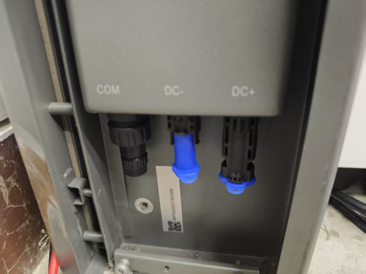
5)Please ensure that the AC-grid port and the AC-backup port are wired securely; otherwise, it may cause equipment damage.
6)After installation, if the system isn't commissioning through Anker SOLIX App, make sure to completely power down the system.
Suggestion:
After installation, commissioning must be performed to update the device firmware to the latest version.
If commissioning is not performed, the system must be completely powered off; otherwise, the battery will deplete in about three days and become permanently damaged.
To power off the system:
1. Press the black start button on the power module for 8 seconds.
2. Toggle the BAT switch on the power module to OFF.
7)After adjusting the device wiring, it is necessary to restart the device.
8)At the initial stage, all switches must be set to the "on" position.
If the BAT switch is not in the "on" position during the commission, the battery may be permanently damaged due to over-discharge during subsequent use.
9)Operation of equipment while it is powered on is not allowed
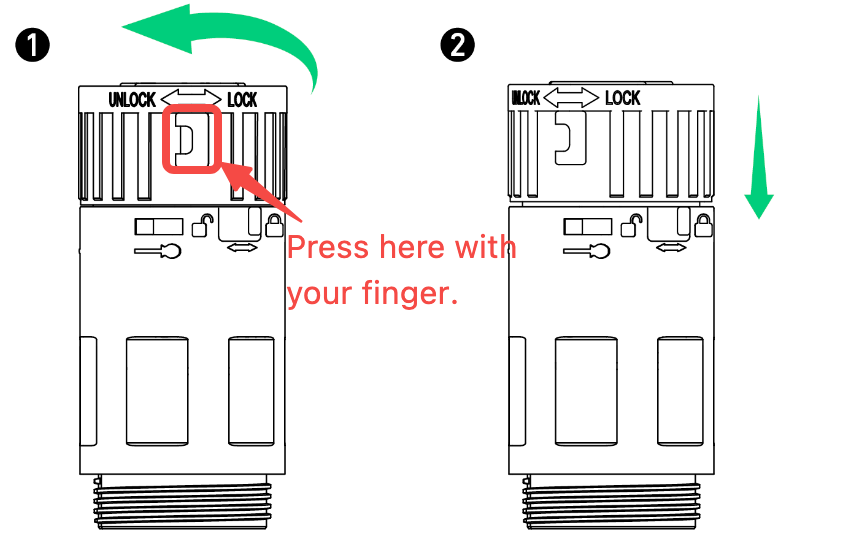
10)How to disassemble the AC-grid terminal and the AC-backup terminal
To disassemble the AC connector, depress the buckle and turn the body to the unlocking icon.
11)Pre-start Preparations for Initial Startup
(1) Ensure that the power cables, meter communication cables, and CT sensors (if any) are all properly connected, and that the wiring sequence of the power cables is correct.
(2) Ensure that the CAN communication link is connected and that the terminal resistor has been installed.
(3) Make sure that the device’s PV switch and Battery (Bat) switch are in the ON position. After confirming that the external PV isolator/PV circuit breaker and Grid isolator/Grid circuit breaker are all in the ON position, proceed with the initial self-check process. This ensures the device can check both internal and external wiring connections as well as the overall system health.
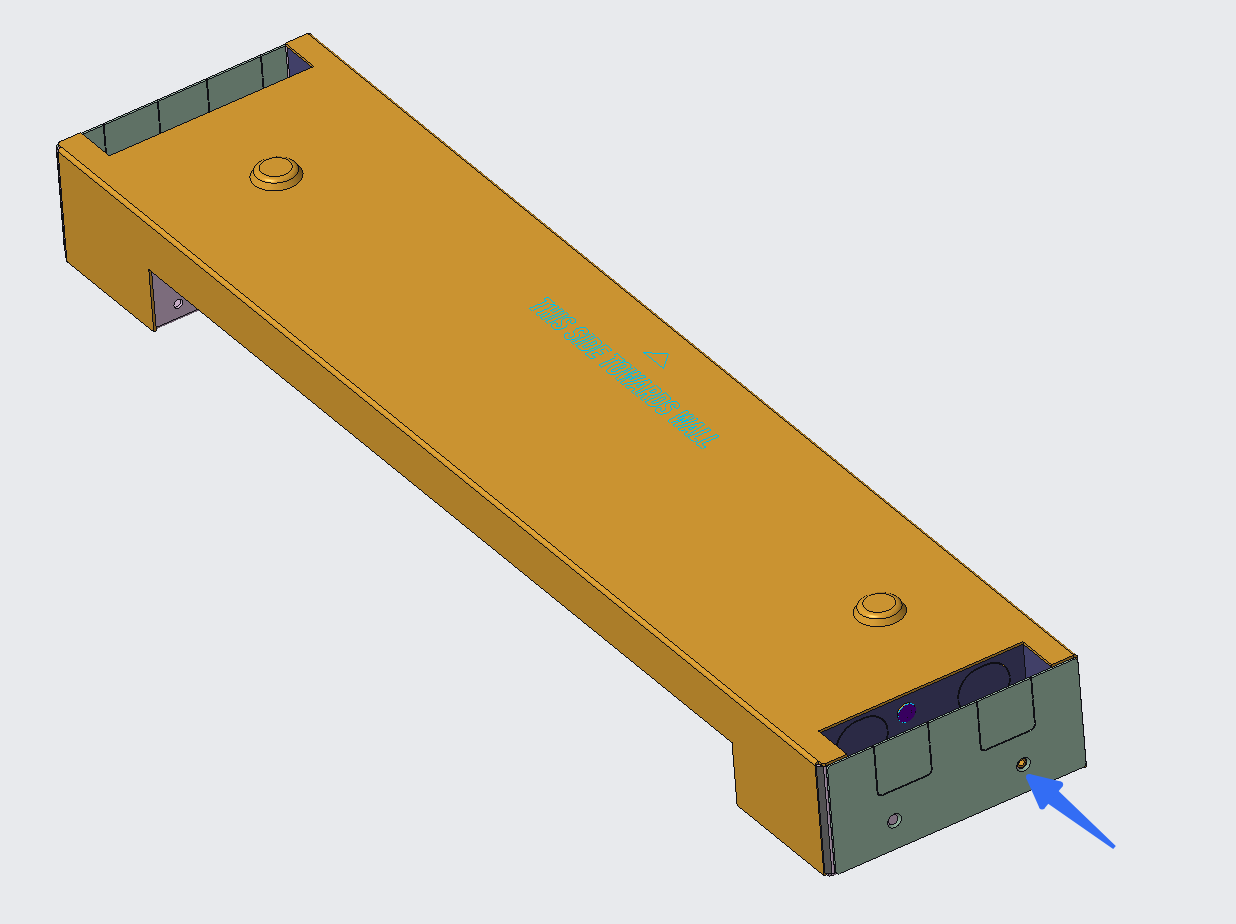
12)Base Baffle Installation Instructions
When the holes of the base and the base baffle do not align, only one screw should be used to install each base baffle during assembly.
The specific scenario is as follows:
-
Install the base baffle on the left side of the base
Align the mounting hole of the base baffle with the mounting hole on the left side of the base (align with the front hole as shown by the arrow in the figure below), then secure it with a screw.
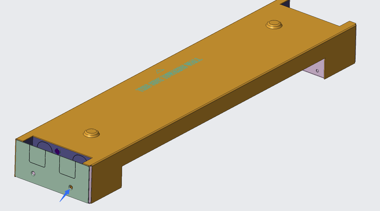
-
Install the base baffle on the right side of the base
Align the mounting hole of the base baffle with the mounting hole on the right side of the base (align with the rear hole as shown by the arrow in the figure below), then secure it with a screw.